
Author: Site Editor Publish Time: 2026-08-10 Origin: Site


Ever wondered how valves in automated systems operate so precisely? Electric valve actuators make this possible. They convert electrical energy into controlled valve movement.
In modern automation, electric valve actuators are vital for efficiency and safety. They are used in many industries, from water treatment to power plants.
In this post, you’ll learn what electric valve actuators are, why they matter, and how they work in various applications.
Electric valve actuators convert electrical energy into mechanical motion to control valve positions. When the actuator receives an electrical signal, its motor starts running. This motor creates rotational force, or torque, which is transferred through a system of gears. The gears adjust the motor’s speed and increase the torque to a level suitable for moving the valve. The output shaft then moves the valve stem or shaft to open, close, or modulate the valve position. This process allows precise control over fluid flow in pipelines or systems.
The electric motor is the heart of the actuator. It provides the initial rotational energy needed to move the valve. Electric motors come in different types, such as AC or DC, depending on the application. However, the motor alone usually spins too fast and with low torque for valve operation.
This is where the gearbox comes in. The gearbox reduces the motor’s speed while multiplying its torque. This torque amplification is essential because valves often require high force to overcome pressure or friction. The gearbox also ensures smooth and controlled valve movement, preventing sudden jerks that could damage the valve or piping.
Together, the motor and gearbox form the powertrain of the actuator, converting electrical power into mechanical motion precisely tailored for valve control.
Electric valve actuators operate using different types of motion to match valve designs:
Rotary (Quarter-Turn) Motion: Most common for ball, butterfly, and plug valves. The actuator rotates the valve shaft 90 degrees to open or close the valve quickly and efficiently.
Linear Motion: Used for gate or globe valves, where the valve stem moves in a straight line to regulate flow. The actuator pushes or pulls the stem up and down.
Spring Return Motion: Includes a spring mechanism that automatically returns the valve to a safe position (open or closed) if power fails. When energized, the motor compresses the spring; if power is lost, the spring drives the valve to its fail-safe position.
Multi-turn Motion: Required for valves that need multiple rotations to open or close fully, such as large gate valves. The actuator rotates the valve stem several turns, providing high torque for heavy-duty operation.
To ensure precise valve positioning, electric actuators often include sensors and feedback systems. Position sensors, such as potentiometers or encoders, monitor the valve’s exact location and send this data back to the control system. This feedback allows the system to confirm that the valve has reached the desired position or to make fine adjustments.
Torque sensors may also be integrated to detect excessive force, preventing damage from obstructions or valve jamming. Limit switches stop the actuator when the valve reaches fully open or closed positions, avoiding over-travel.
These sensors improve reliability, safety, and automation by enabling real-time monitoring and control of valve operation.
Understanding the key components of an electric valve actuator helps you grasp how it reliably controls valve operation. Each part plays a vital role in converting electrical power into precise mechanical motion.
The electric motor is the actuator’s powerhouse. It converts electrical energy into rotational motion. This motor can be AC or DC, depending on the system requirements. It drives the actuator’s output shaft, producing torque to move the valve. The motor’s speed and torque determine how fast and forcefully the valve can open or close.
Motors are designed for durability and efficiency. Some include thermal protection to prevent overheating during extended use. The motor’s performance directly affects actuator responsiveness and reliability.
Direct motor output usually spins too fast and lacks sufficient torque for valve operation. The gear system solves this by reducing speed and amplifying torque. Through a series of gears—often worm gears or planetary gears—the motor’s high-speed rotation slows down while torque increases.
This torque amplification is crucial for moving valves against pressure or friction. The gear system also ensures smooth, controlled valve movement, preventing sudden jolts that could damage equipment.
The control unit acts as the actuator’s brain. It receives electrical signals from a control system or operator and manages motor operation accordingly. Many control units offer features like:
Position feedback to confirm valve position
Remote operation via digital or analog signals
Fault diagnostics and status monitoring
This enables seamless integration into automated systems, allowing operators to control valves from a central location.
Power failures or control system faults can disable automated valve operation. To maintain safety and control, electric actuators often include a manual override. This mechanism typically involves a handwheel or lever that lets operators manually move the valve.
Manual override ensures the valve can be positioned safely during emergencies or maintenance. It provides a fail-safe option when electrical control is unavailable.
Safety and precision are critical in valve control. Limit switches detect when the valve reaches fully open or fully closed positions. They stop the motor to avoid over-travel, protecting the valve and actuator from damage.
Torque sensors monitor the force applied by the actuator. If excessive torque is detected—indicating valve obstruction or jamming—the actuator can halt operation to prevent mechanical failure.
Together, these components ensure the actuator operates safely, reliably, and with precise control.
Electric valve actuators come in several types, each designed to meet specific industrial needs. Understanding these types helps you choose the right actuator for your application, ensuring optimal performance and reliability.
Standard electric actuators are the most common type. They provide reliable, stable operation for a wide range of valves, including ball and butterfly valves. These actuators are ideal for applications like water treatment plants, HVAC systems, and general industrial pipelines.
They typically offer straightforward on/off control or simple modulating capabilities. Their design focuses on durability and cost-effectiveness, making them a practical choice for many automation projects.
Intelligent electric actuators incorporate advanced digital control technology. They can communicate with control systems using protocols like Modbus or HART, enabling remote monitoring and precise valve positioning.
Features often include:
Real-time position feedback
Fault diagnostics
Adaptive control algorithms
Energy-saving modes
These actuators suit industries aiming for higher automation levels, such as chemical processing, power generation, and smart manufacturing. They help reduce downtime and improve process efficiency.
In hazardous environments—oil refineries, chemical plants, mining—safety is critical. Explosion proof electric actuators are designed to prevent sparks or electrical faults from triggering explosions.
They feature robust housing, special sealing, and certified components compliant with standards like ATEX or IECEx. These actuators ensure safe valve operation where flammable gases or dust may be present.
Choosing explosion proof actuators protects personnel, equipment, and facilities while maintaining automation benefits.
Heavy duty electric actuators deliver high torque and durability for demanding applications. They handle large valves and frequent cycling in harsh environments.
Typical uses include:
Large pipeline systems
Power plants
Mining operations
High-pressure fluid control
These actuators are built with reinforced gearboxes, powerful motors, and rugged materials. They provide long service life and reliable valve operation under tough conditions.
Tip: Match actuator type to your environment and control needs—standard actuators for simple tasks, intelligent for smart control, explosion proof for hazardous zones, and heavy duty for high torque demands.
Application Requirement | Recommended Actuator Type |
|---|---|
General valve automation | Standard Electric Actuator |
Remote monitoring and smart control | Intelligent Electric Actuator |
Hazardous or potentially explosive areas | Explosion-Proof Electric Actuator |
Large valves and high torque requirements | Heavy-Duty Electric Actuator |
Advanced process automation | Intelligent Electric Actuator |
Harsh industrial operating conditions | Heavy-Duty Electric Actuator |
Selecting the right electric valve actuator ensures your system runs smoothly and safely. Several key factors help you make the best choice for your application.
Torque is the force needed to move a valve. It’s crucial to pick an actuator that can provide enough torque to operate your valve under all conditions. Start by finding the valve’s maximum required torque, often called breakaway torque. This is usually higher than the torque needed to keep the valve moving once it starts.
To avoid undersizing, multiply the valve’s maximum torque by a safety factor—commonly 1.3. For example, if your valve needs 100 Nm torque, the actuator should supply at least 130 Nm. This extra capacity accounts for wear, pressure changes, or unexpected resistance.
Also, consider the actuator’s power supply voltage and type (AC or DC). Ensure it matches your system’s available power to prevent compatibility issues.
Actuators must fit your valve mechanically. ISO 5211 is an international standard that defines mounting flange dimensions and drive shaft sizes for valve actuators. Choosing an actuator that complies with ISO 5211 simplifies installation and allows easy interchange between brands.
Check the actuator’s output shaft type and size to match your valve stem or shaft. Some valves require specific adapters or custom mounts. Confirming this compatibility upfront saves time and prevents costly modifications.
Your actuator will face environmental challenges that affect durability and performance.
Temperature Range: Verify the actuator can operate reliably in your site’s temperature extremes, from freezing cold to high heat.
Ingress Protection (IP) Rating: This rating shows how well the actuator resists dust and water. For outdoor or wet environments, an IP65 or higher rating is recommended.
Certifications: If your application involves hazardous locations, look for explosion-proof certifications like ATEX or IECEx. These ensure the actuator meets safety standards for flammable gases or dust.
Different applications require different control types:
On/Off (2-Point) Control: The simplest form, where the valve is either fully open or fully closed.
3-Point Control: Allows the valve to stop at intermediate positions using separate signals for open, close, and stop.
Modulating Control: Provides precise valve positioning anywhere within the range. This is ideal for flow regulation or processes needing fine adjustments.
Choose an actuator control type that matches your process requirements and control system capabilities.
Actuator housing materials affect resistance to corrosion, impact, and temperature.
Plastic: Lightweight and corrosion-resistant, suitable for low-stress environments.
Aluminum: Offers good strength and heat resistance, common in industrial settings.
Stainless Steel: Best for harsh or corrosive environments like chemical plants.
Match material choice to your environment and media to ensure long-lasting performance.
Tip: Always verify actuator torque exceeds valve requirements by at least 30%, confirm ISO 5211 compatibility, and select materials and IP ratings suited for your environment to ensure reliable, trouble-free operation.
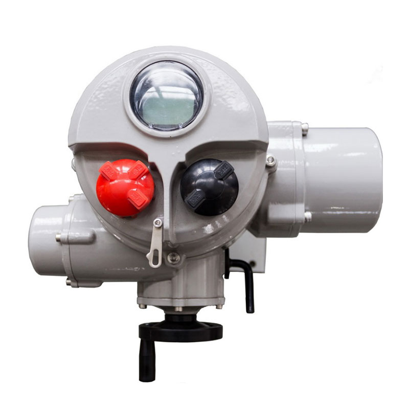
Electric valve actuators include various features to ensure reliable, safe, and precise valve operation in diverse industrial settings. These reliability mechanisms protect the actuator and valve, maintain system integrity, and enable smooth control under normal and emergency conditions.
Fail-safe features automatically move the valve to a safe position during power loss or system failure.
Spring Return: A mechanical spring stores energy when the valve is powered. If power fails, the spring releases to drive the valve to a preset fail-safe position, either fully open or closed. This ensures safety without external power.
Battery Backup: Rechargeable batteries provide temporary power to the actuator, allowing it to move the valve to a safe position during outages. This is useful when a spring return is not practical or when precise control during power loss is needed.
Manual override allows operators to control the valve manually if the actuator loses power or malfunctions. Usually implemented as a handwheel or lever, it enables safe valve positioning during emergencies or maintenance. This feature is critical for maintaining control and preventing system downtime.
Limit switches detect when the valve reaches fully open or fully closed positions. They automatically stop the actuator motor to prevent over-travel that could damage the valve or actuator. Many actuators have adjustable limit switch cams, allowing customization of end positions to suit specific operational needs.
Torque sensors monitor the force applied by the actuator. If the torque exceeds a set threshold—indicating valve obstruction, jamming, or mechanical failure—the actuator can halt operation. This protects the valve and actuator from damage, reducing repair costs and downtime.
The duty cycle defines how long the actuator motor can run before needing a rest. Exceeding this can cause overheating and damage. Thermal protection sensors detect motor temperature and automatically shut down or reduce power to prevent burnout. These features extend motor life and ensure reliable operation in continuous or heavy-use applications.
Position feedback devices, like potentiometers or encoders, provide real-time valve position data to the control system. This ensures precise valve positioning and enables modulating control, where the valve can be opened to any position within its range for fine flow regulation. Modulating units accept input signals (e.g., 4–20mA, 0–10V) and send feedback signals for closed-loop control.
An internal heater prevents condensation and keeps lubricant grease fluid in cold or humid environments. This avoids freezing or corrosion inside the actuator, ensuring reliable startup and operation in harsh climates or outdoor installations.
Local control units provide manual control options directly on the actuator. Operators can switch between local and remote modes and use selector switches to open, close, or stop the valve on-site. This feature is vital during maintenance, commissioning, or when remote control is unavailable.
Electric valve actuators offer numerous advantages that make them a popular choice across many industries. Their ability to improve automation, precision, and efficiency helps modern systems run smoothly and reliably. Below are some key benefits that highlight why electric actuators stand out.
One of the biggest perks is remote operation. Electric actuators can be controlled from a central control room or even remotely via networked systems. This eliminates the need for manual valve adjustments on-site, especially useful for valves located in hard-to-reach or hazardous areas. Centralized control also allows operators to monitor valve status and respond quickly to process changes or emergencies, improving safety and efficiency.
Electric actuators provide highly accurate valve positioning. They can modulate valve openings to exact percentages, enabling fine control over fluid flow rates. This precision is essential in processes where maintaining specific flow conditions is critical, such as chemical dosing, HVAC systems, or water treatment plants. The integration of position feedback sensors ensures the valve reaches and holds the desired position consistently.
Compared to pneumatic or hydraulic actuators, electric actuators have fewer moving parts and no need for compressors or fluid lines. This simplicity results in lower maintenance requirements and fewer potential failure points. Without the need for air or hydraulic fluid, there's no risk of leaks or contamination, reducing downtime and repair costs over time. The overall lifecycle cost of electric actuators is often lower, making them a cost-effective solution.
Electric actuators consume power only when operating, unlike pneumatic systems that require continuous compressed air supply. This makes them more energy-efficient, especially in systems with frequent valve cycling or modulating control. Some models feature variable speed drives that adjust motor power based on demand, further reducing energy consumption. This efficiency contributes to lower operational costs and supports sustainability goals.
Electric actuators operate quietly and cleanly since they do not rely on noisy compressors or hydraulic pumps. There are no fluid leaks or air emissions, making them ideal for environments where cleanliness and noise control matter, such as food processing plants, hospitals, or laboratories. Their silent operation also contributes to a safer and more comfortable workplace.
Electric valve actuators offer precise control, energy efficiency, and low maintenance for various industries. Choosing trusted manufacturers ensures reliable products and support. Emerging technologies enhance actuator intelligence and safety features. Buyers and engineers should prioritize compatibility, safety, and control options for optimal performance. Hengchun Actuator provides advanced electric valve actuators that deliver exceptional reliability and innovative features, adding significant value to your automation systems. Trust Hengchun Actuator for durable and efficient valve control solutions.
A: An electric valve actuator is a device that converts electrical energy into mechanical motion to control valve positions, enabling precise flow regulation in pipelines.
A: It uses an electric motor to generate torque, which is amplified by a gearbox to move the valve stem or shaft, controlling valve opening or closing.
A: Electric valve actuators offer precise positioning, lower maintenance, energy efficiency, and quieter operation compared to pneumatic or hydraulic systems.
A: Common problems include motor overheating, torque sensor faults, or limit switch failures; troubleshooting involves checking electrical connections, sensor calibration, and manual override function.
A: Prices vary by type and features, ranging from affordable standard models to higher-cost intelligent or explosion-proof electric valve actuators for specialized applications.


